9. Interlocking mechanism.
(1) The function of the interlock mechanism is to make the position of the paper on the paper transport board fixed when the machine fails. Swinger does not send paper. The purpose of the interlocking mechanism is fourfold:
1 To protect the printed product: After the interlock mechanism is actuated, the printed sheet is fixed on the paper transport board. When the trouble is eliminated, the paper can still be used continuously. Otherwise, if the paper is skewed and the paper-feeding teeth continue to transfer, the left and right mouths will not be the same, the overlay accuracy will be destroyed, and a series of printing failures such as ghosting and wrinkling may occur.
2 Protective rubber: The rubber acts as a transfer ink. If two or more sheets of paper enter the surface and are damaged, the ink transfer is destroyed and the quality of the print cannot be guaranteed. Changing or shimming the rubber is very troublesome.
3Protect the roller tooth row: When the mouth is uneven, the paper will slide easily in the tooth row. As time goes by, it will cause the tooth pad to wear and the overlay accuracy will be affected.
4 protect the machine: When the paper into a sheet or a foreign body between the drum, the machine will be subject to a sudden impact, the drum surface, bearings and gears, etc. may be destroyed. The interlocking mechanism can be said to be the last safety line.
(2) The action of the interlocking mechanism is divided into two major parts
1 Stop the paper on the paper feeder: There are many ways to stop the paper on the paper feeder. Heidelberg presses use suction underneath the paperboard and press paper on the paperboard. The domestic equipment uses suction under the paperboard and the front gauge stops on the paperboard. The former regulations stop on the paperboard or on the paperboard. The paper press has special agency control.
2 The paper feed tooth is not on the paperboard: This action is achieved by the movement of the open tooth cam. No matter what kind of organization is adopted, the final result is the same. After the paper teeth have left the paper feeder, they still close their teeth because the teeth have left the paper.
3 The action process of the interlocking mechanism: a. The photoelectric sensor identification signal is transmitted to the main console; b. The main console analyzes and informs the corresponding control switch; c. The control switch starts and the actuator starts to work.
The important role of the interlocking mechanism determines that it must always be in normal working condition.
10. Analysis of the movement process of paper in the paper feeding section. The paper is accelerated by the paper feed nozzle by the paper roll at the paper stack. After the take-up roller conveys it to the regulatory part, it is stationary again. During this period, the paper undergoes a process of acceleration, deceleration, and reacceleration. The paper acceleration process is obvious, but how does the paper deceleration process be realized?
(1) The frictional force that drives the forward movement of the paper no longer exists at the constant speed when the paper arrives at the paper feeding board, but when the front paper exits the belt, the frictional force that is driven at this time is gradually reduced. After a paper feed step has elapsed, the paper has completely left the paper feed belt. The paper moves forward only by its inertia. Due to the frictional resistance, its inertia gradually decreases, which reduces the speed of the paper.
(2) The angle of the front plate is not the same as the angle of the platen. The angle of the front plate is smaller than the angle of the platen so that the direction of the paper uploaded from the platen changes, thus changing its speed. Through the speed analysis we can know that the speed is reduced.
(3) After the deceleration of the front sheet, the arrival of some paper to the front gauge, and some to the far, but if the paper has reached zero before the rules, then the former rule will not be able to make up for the paper feeding error. To the role of positioning. Therefore, when the paper arrives at the front gauge, the speed should be slightly greater than zero. To prevent the paper from bouncing, a brush wheel is added to the tail of the paper to absorb the amount of rebound. The subsequent paper also has a certain obstruction effect on the rebound of the paper.
11. Adjustment of the paper feeding section.
(1) Benchmarks. The starting point of all actions and behaviors. There is only one starting point, and this starting point is called the absolute benchmark. For a machine, the machine's benchmarks include design references, machining references, and installation and commissioning benchmarks. Relative benchmarking: This action and behavior starts with an absolute benchmark, but it is also a starting point for other actions and behaviors. This starting point is called relative benchmark. Relative benchmarks are generally more than one, but their status is not the same.
The absence of a benchmark is tantamount to the absence of a starting point for action and behavior. All actions and behavior must be chaotic. Therefore, when designing, processing, installing, and debugging the machine, it is necessary to find its reference and relative reference, otherwise the machine cannot be manufactured.
(2) Adjustment base. The starting point for the time and displacement of all parts of the machine, this benchmark is only one, called the absolute benchmark of the machine.
In addition to the absolute reference, there is the relative reference of the adjustment machine. It refers to the time and displacement of a part as the starting point of the absolute reference of the adjustment machine, but other parts take this part's time and displacement as the starting point, and then put this part It is called the relative benchmark of the tuning machine. There are usually more than one relative reference for the tuning machine.
Absolute benchmarks and relative benchmarks are the basis for machine regulation. No benchmarks or relative benchmarks can be found and regulation cannot be carried out. Having mastered the absolute benchmarks and relative benchmarks, debugging has reduced blindness, which is also one of the so-called shortcuts to tuning.
(3) Absolute reference of printer adjustment and relative reference of adjustment The adjustment reference of the printer differs depending on the model, but there is only one absolute reference for adjustment. Some of the absolute standards for machine debugging are impression cylinders, and some are registration rollers. At present, the absolute benchmark for multicolor printing presses is the registration roller (see the transfer paper tooth as part of the registration roller). It does not matter which of the absolute benchmarks of the tune machine is selected, but once it is selected, it cannot be changed halfway, otherwise everything will need to start from scratch. In other words, the absolute benchmark is not adjustable. The relative reference depends on the drive train.
(4) The time and displacement of the components of the drive chain are linked in a certain sequence. This chain is called the drive chain. The non-adjustable point on the drive chain is the absolute reference of the machine. In addition to the absolute reference point on the drive chain and the last point on each branch (in addition to the main chain and sometimes many branches on the transmission chain), all other points are on the drive chain. All can be called relative benchmarks.
Therefore, when debugging the machine, first analyze the transmission chain clearly, and then find the color reference and relative reference of the tuning machine on the transmission chain. In addition, there must also be a graph of the time and displacement of the components relative to the absolute reference and the relative reference. This can be done in a regulatory manner when adjusting the machine. This is the most basic method of tuning, and it can also be called tuning principle.
(5) The transmission chain of the paper feeding section of the paper feeding section is as follows:
Register rollers - Rules section - Conveyor - Feeder - Feed pile
In this drive chain, the register roller is the absolute reference of the adjustment machine. Other than the paper pile, it can be called the relative reference of the adjustment machine. However, these relative positions are different. The closer to the absolute reference, the higher the level is. The others, then the second one, can be divided into the first, second, ... relative benchmark based on the distance relationship with the absolute benchmark. Here, the rules section is the first relative benchmark, the paperboard is the second relative benchmark, and Feida is the third relative benchmark. An absolute reference and a relative reference of the paper feeding portion are found, and a time-and displacement-displacement diagram of each component and the reference and the relative reference is prepared, and the paper feeding portion can be adjusted. The specific approach is briefly described as follows:
A set of collimator rollers is used as a reference. Once its position is determined, it cannot be adjusted relative to any other component.
2 Regulation is relative to the registration roller (or referred to as paper-feeding teeth) adjustment: When the registration roller is on the feeding paper, if the pick-up time is wrong, then only the regular part can be adjusted, and the registration roller cannot be adjusted. tooth).
The matching relationship between the register roller and the rules is as follows: When the register roller is on the paper feeding conveyor, the regulatory part has been positioned, the transfer tooth and the regulatory part are transferred for a certain period of time, the front regulation hem, and the paper handing The crepe paper leaves the paperboard, and then the front gauge returns to the paperboard to position the follow-up paper. After the paper teeth are swung back, the second paper is started.
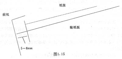
(Figure 1.15)
3 The adjustment of the paperboard relative to the rules: When the current rules just reach the paperboard, the front paper of the paper passing over the paperboard should be about 5mm from the front gauge. Why do you want to stay 5mm? The main consideration is the stability time of the front gauge, because the swing of the front gauge is driven by the cam. The front gauge stops on the paperboard, just in contact with the rocker mechanism at the highest point of the cam. This is a filter point for the cam. Because the inertia of the front gauge exists, the front gauge cannot be in an absolutely stationary state at this point, so the front gauge requires a settling time. Some people think that 5mm is used for paper deceleration. This understanding is incorrect. Because the distance from the paper feeder to the front gauge is always constant, and the paper feeder is always running at a constant speed, the speed of the paper is the same each time it reaches the front panel. Assuming that the speed of the machine is constant, the way to slow down is to increase the displacement, but in fact the travel of the paper on the front plate is not increased by the 5mm, then how can it be said that it acts as a deceleration? From another point of view, If the 5mm distance has played a deceleration effect, then after the speed of the machine changes, the 5mm distance should also change accordingly. The speed is higher and the distance is larger; the speed is lower and the distance is smaller. This assumption does not actually exist at all.
How to ensure the distance of 5mm? The only way is to adjust the fit between the paperboard and the front gauge. This adjustment is generally in the paper machine drive surface, through the change of the position of the gear or chain to change the relationship between them, so as to achieve the predetermined requirements.
4 Feida's adjustment with respect to the paperboard: During normal operation, Feida should transfer the paper through the take-up roller by about 5mm. At this time, the pressure roller can press down. If this mismatch is found, Feida should be adjusted. At present, the feeder of the film machine is generally driven by a universal joint, and the position of the long hole on the flange of the universal joint end can be changed.
5 Adjustment of the paper stack relative to Feida: When the pile of paper and Feida are not fit together, the stack should first be adjusted, ie the stack should be in a free state.
The above describes briefly the adjustment between the paper feeding sections. The internals of each component can also be adjusted in accordance with this relationship. However, one thing to note is that it must not be reversed, that is, the reference cannot be reversed.
The components that are relatively complex in the assembly are feeders and rules. The rules have been described before. Take Feida as an example to analyze the internal adjustment methods of the components. The relative movements of the components in Feida are fixed at the time of design, generally not adjustable, and can only be adjusted when overhauled, but the analysis of the relationship between the internal components of the Feida is very important to Feida. beneficial. The roles of the delivery nozzle, the dispenser nozzle, and the presser foot have been described before. From the drive chain, the mutual relationship between them should be: the paper-feed nozzle is a paper-subtracting nozzle-presser foot. Feeding the paper nozzle is the absolute benchmark of the Feida internal debugging. The paper suction only can be adjusted relative to the paper feeding nozzle, but it is relative to the presser foot. In other words, when the fit between the delivery nozzle and the dispenser nozzle is incorrect, the paper suction nozzle should be adjusted; when the relationship between the separator nozzle and the presser foot is not correct, the presser foot should be adjusted. This clarifies the relationship between the three components.
(6) The application of the symmetry principle in the adjustment of feeders, from Feida, to paperboard, to the former gauge, it can be seen that most of the components on it are symmetrical. For this reason, the adjustment of these components must be based on the principle of symmetry, that is, symmetrical position, symmetrical force, and symmetrical adjustment. This is the key to ensure the normal operation of the machine. However, in the actual process, the ideal symmetry does not exist, then is it normal operation will be destroyed? In fact there is no. Why? This is because the rules partially compensate for the paper feeding error. What actually compensates is the error caused by these asymmetrical factors. However, the error that this can make up for is limited. When the error in paper feeding exceeds a certain level, the rules will be powerless and can only give a wrong signal. The method of solving this problem can only adopt the principle of quasi-symmetry. In practical work, all parts should work in the quasi-symmetrical principle, and try to make it approach the ideal symmetry state as much as possible. This is one of the primary conditions for tuning.
Shaker Bottle,Protein Shaker,Protein Shaker Bottle
Sports Water Bottle Pill Box Co.,Ltd , http://www.nspillbox.com